Сделал блок питания в стиле макоронного монстра сегодня:
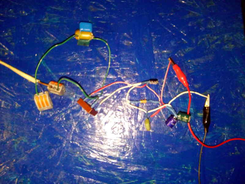
Made a spaghetti monster style power supply today.
Уже давно мне хотелось сделать датчик движения для включения и выключения света в некоторых местах. Для этого заранее приобрёл у китайских товарищей охапку датчиков, микроконтроллеров и реле - с этим не было проблем, проблемы были с блоками питания для этого. Как показывает практика автоматизации бытовых рутинных действий - блоки питания - это то, что вероятнее всего выйдет из строя через некоторое время при постоянном использовании. Поэтому решил попробовать сделать бестрансформаторный блок питания, для этого взял первую попавшуюся схему и более или менее подходящие радиодетали из старой электроники:
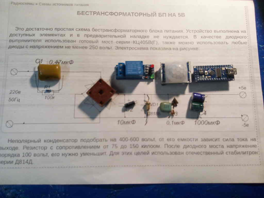
I wanted to make a motion sensor to turn on and off the light in some places. To do this, i bought a bunch of sensors, microcontrollers and relays from Chinese comrades in advance - there was no problem with it, but there were problems with power supplies for this. As the practice of automation of household routine actions shows - power supplies - is what will most likely fail after some time with constant use. Therefore, i decided to try to make a transformerless power supply unit, for this purpose i took some scheme and more or less suitable radio components from the old electronics.
Плёночный конденсатор C1 - это ключевой элемент этого блока питания. У меня не было необходимых высоковольтных - поэтому сначала я использовал те, что на 250 вольт. Оказалось, что 0.44 микрофарад - этого достаточно для микроконтроллера, но уже недостаточно для работы реле. Также после 15 минут работы, 250 вольтные конденсаторы не выдержали нагрузки (их "пробило"). Поэтому в финальной схеме блока питания для этого незамысловатого устройства указан конденсатор ёмкостью 1 микрофорад 630 вольт:
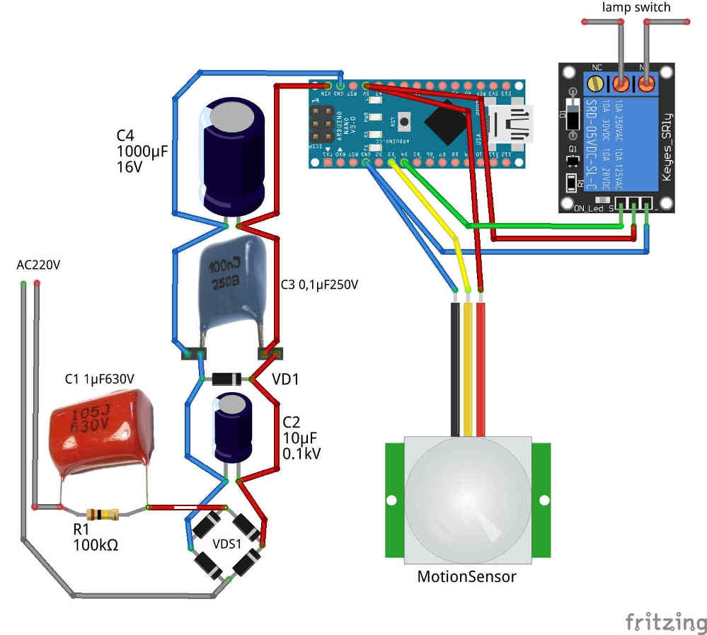
The C1 film capacitor is a key element of this power supply. I didn't have the necessary high voltage capacitors - so i used the 250 volt capacitors first. It turned out that 0.44 micro-farad is enough for a microcontroller, but not enough for relay operation. Also after 15 minutes of operation, the 250 volt capacitors could not withstand the load (they were "punched"). Therefore, in the final circuit scheme of the power supply for this simple device is indicated film capacitor of 1 microforade 630 volts.
Вот так выглядит всё собранное устройство в стиле "макароны на брёвнышке" (использовал 4 последовательно-параллельно соединённых старых советских конденсатора 1 микрофарад 160 вольт, чтобы получить из них 1 микрофарад 320 вольт), украшенное примитивистскими орнаментами:
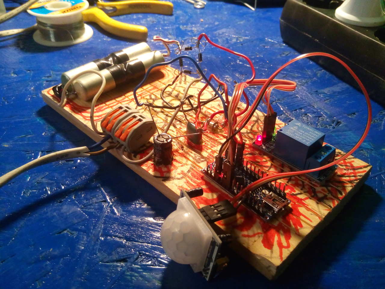
This is how the whole device looks like in the style of "macaroni on a log" (used 4 sequentially-parallel connected old soviet capacitors 1 microfarad 160 volts to get from them 1 microfarad 320 volts), decorated with primitive ornaments.
Раньше, чтобы набрать зерна из ларца приходилось включать свет:
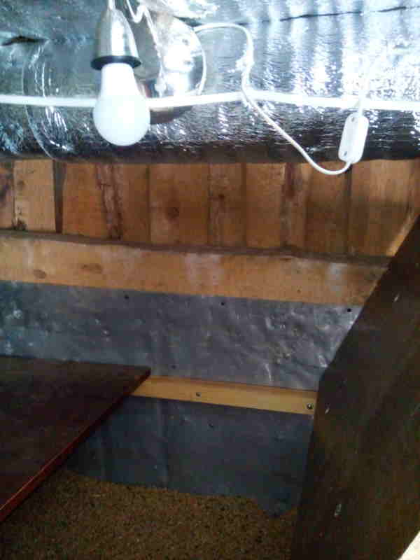
I used to have to turn on the lights to get the grains out of the chest.
Теперь свет загорается если есть движение в помещении:
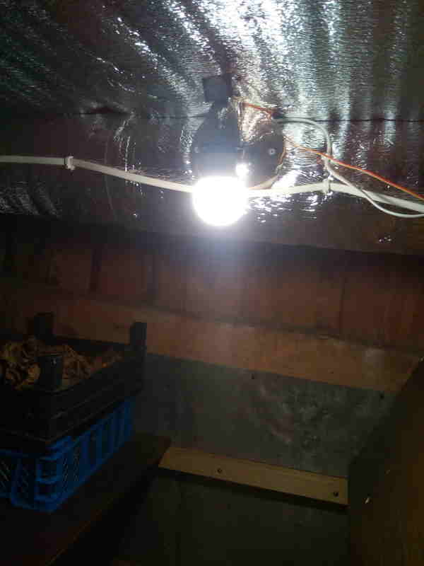
Now the light comes on if there's movement in the room.
Также стоит отметить, что для диодного моста VDS1 подойдут любые высоковольтные диоды, а стабилитрон VD1 оптимальнее всего подбирать для получения 7-9 вольт (я использовал старый Д814А, дающий 7,8 вольта). Для питания микроконтроллера необходимо 6-12 вольт.
На выходное напряжение в этом блоке питания влияют характеристики стабилитрона VD1. На выходную силу тока влияет ёмкость конденсатора C1.
It is also worth noting that for the diode bridge VDS1 will be suitable any high-voltage diodes, and Zener diode VD1 is best selected to obtain 7-9 volts for result (i used the old Д814А, giving 7.8 volts). To power a microcontroller it is necessary to supply 6-12 volts.
The output voltage in this power supply unit is affected by the characteristics of Zener diode VD1. The output current is affected by the capacitance of the capacitor C1.
Вероятно, позже добавлю модуль фоторезистора (для уличной лампы, чтобы не включалась днём) и сетевого устройства (для удалённого управления освещением и обработки данных с сенсора).
А вот код для контроллера:const int lightDelay = 90000;
const byte movePin = 3;
const byte relayPin = 4;
long lastmoveMillis = 0;
void setup() {
pinMode(movePin, INPUT);
pinMode(relayPin, OUTPUT);
digitalWrite(relayPin, HIGH);
}
void loop() {
if (digitalRead(movePin) == 1) lastmoveMillis = millis();
delay(100);
if (lastmoveMillis > 0) activateRelay();
}
void activateRelay() {
if ((millis() - lastmoveMillis) < lightDelay) digitalWrite(relayPin, LOW);
if ((millis() - lastmoveMillis) > lightDelay) {
digitalWrite(relayPin, HIGH);
lastmoveMillis = 0;
}
}
Here's the code for the controller. Probably later i'll add a photoresistor module (for street lamps not to be switched on during the day) and a network device (for remote lighting control and sensor data processing).
#
automation #
hardware #
lightning #
microcontrollers #
motion #
photo #
powersupply #
programming #
recycling #
sensor #
relay #
technology